UNDERSTANDING THE FRAME

Understand how an LSF frame carries loads, achieves stability and is prepared

Light Gauge Steel Framing (LGSF), also known as Light Steel Framing (LSF), is a construction system whose load-bearing skeleton consists of cold-formed, thin-walled galvanised steel sections. Studs, tracks, joists, trusses, stability components, connections and anchors are organised to resist the actions applied to the building and transfer their effects through to the supports and foundations.

C and U sections do not become a frame simply by being placed next to one another. Their section size, thickness, orientation, spacing, supports and connections depend on the function they perform and the forces they must resist.

At Algeria Light Steel, the load-bearing arrangement is defined for each project. The architectural data is transformed into a structural model and then into approved documentation that links the calculations and drawings to every component to be manufactured and its position in the building before factory production begins.

LSF forms the load-bearing frame, not the finished building. Thermal, acoustic, fire, hygrothermal and weathertightness performance depends on the complete build-ups, their junctions, their installation and the selected scope of study.

EXPLORE THE FRAME IN 360°

Follow the continuity of forces through the complete skeleton

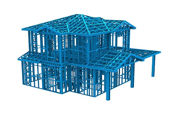
Rotate the frame to see how the load-bearing walls, openings, floors, trusses, stability systems and anchors form a single structural assembly.

Vertical loads must travel from the roof and floors into the load-bearing panels and then through to the supports. Horizontal actions must be collected, redistributed and transferred to the stability components and foundations. Connections maintain continuity between these subassemblies.

This view illustrates a structural principle. It is neither a house model offered for sale nor fabrication documentation that can be transferred to another project. Section geometry, reinforcements, connections and anchors remain determined by the engineering for each building.

LSF frame in 360°Drag to rotate the frame.

FROM ENGINEERING TO PRODUCTION

Six stages that turn a project into a manufacturable frame

Each stage produces the information required by the next. Manufacturing therefore begins not with the choice of a section, but with the progressive definition of a calculated, detailed and sufficiently coordinated load-bearing system that can be produced.

  1. 01 — Establish the design inputs

    The study gathers the data that determines the behaviour of the frame: drawings or brief, building use, geometry, levels, spans, openings, permanent and imposed loads, equipment, support conditions, site data, and the climatic or seismic actions to be considered.

    Interfaces with the foundations, floors, roof, façades, windows and doors, and building services are also identified. Transport, lifting and erection constraints are incorporated as soon as they may influence panel breakdown or the level of prefabrication.

    Any input that is missing, contradictory or still liable to change is flagged before the affected components are frozen.

  2. 02 — Establish the structural scheme and load paths

    The project is translated into a structural arrangement: grids, load-bearing panels, studs, tracks, joists, trusses, lintels, jamb studs, reinforcements, bracing, any diaphragms, connections and anchors.

    This stage defines spans, supports, continuities, interruptions created by openings and the transfers required between different parts of the building. It also identifies primary and secondary elements, and the components whose function is to stabilise or restrain the sections.

    The model must provide a continuous path for both vertical loads and horizontal actions. A reaction from a truss, joist or lintel must reach a component capable of receiving it and transferring it through to the supports.

  3. 03 — Define actions and design situations

    Self-weight, other permanent loads, imposed loads, wind and, where required by the project, seismic or special actions are defined and combined according to the building’s use, location and the applicable standards.

    The model establishes the axial forces, moments, shear forces, support reactions and displacements associated with the different situations. The study distinguishes strength and stability checks from serviceability criteria such as deflection, vibration and horizontal movement.

    The governing situation may differ from one component to another: compression for a stud, bending and vibration for a joist, shear for a stability panel, uplift for a truss, or combined tension and shear for an anchor.

  4. 04 — Size the components, connections and interfaces

    Section sizes, thicknesses, spacings, reinforcements and restraints are defined according to the calculated forces. Verification takes account of the particular behaviour of thin-walled sections, their supports, perforations and the restraints actually provided in the building.

    Connections are designed as part of the load-bearing system. Fastener type, diameter, number and arrangement are determined by the forces to be transferred, the connected thicknesses, edge distances and any eccentricities.

    Openings, service holes, applied loads and interfaces with foundations or other construction systems are detailed before being incorporated into the manufacturing data.

  5. 05 — Freeze the Approved for Fabrication documentation

    Drawings, dimensions, openings, supports, sections, connections, perforations, service holes and interfaces affecting the frame are brought together in the documentation submitted for Approved for Fabrication.

    Approval freezes the technical basis from which the production data can be generated. Every component then receives a precise definition: section type, length, cut, perforations, service holes, orientation and identification mark.

    A change introduced after this milestone is not treated as a simple graphic correction. If it affects a load, span, support, opening, connection or load path, its consequences must be reassessed before it is incorporated.

  6. 06 — Manufacture, identify, inspect and prepare for delivery

    At the factory, coils of galvanised steel are transformed by cold roll-forming. Components are cut, perforated and marked in accordance with the applicable documentation.

    They are then identified and grouped by panel or subassembly for delivery as prepared sections, or assembled into panels, trusses and other units where required by the selected level of prefabrication.

    Inspections cover, in particular, correspondence with the production data, component identification, dimensions, perforations and subassembly composition. Grouping or loading order is coordinated with the intended assembly and erection sequence.

COMPONENTS AND FUNCTIONS

Understand the role of each component family

The structural scheme defines where forces travel. The components give it physical form. Their function depends on their geometry, position in the building and the connections between them.

Forming wall panels

Vertical studs carry the loads transferred by the components above and may also be subject to wind pressure or suction. Their section size, thickness, spacing, unrestrained height and restraint conditions directly influence their strength and stability.

Top and bottom tracks position the studs, distribute certain forces and maintain continuity with adjacent panels, floors, roof and supports. A load-bearing panel must therefore be engineered as a connected subassembly, not as a series of independent studs.

Spanning between supports

Joists carry floor loads or the loads from certain roofs and transfer them to the walls, beams or other components supporting them. They are checked primarily for bending and shear, but lateral stability, deflection and floor vibration may also govern.

Trusses organise the transfer of roof loads through their chords and webs. Their behaviour depends on the overall geometry, supports, connections between members and systems restraining the compression chords.

Redirecting forces around openings

A door, window, stairwell opening or service passage interrupts the regular grid. Loads that would have passed through that area must be redirected to adjacent components and then returned to the load path.

Lintels, jamb studs, reinforced studs, supports and transfer components are defined according to the opening width, loads from the levels above and the available support conditions. Changing the size or position of an opening may therefore affect several components beyond its immediate perimeter.

Stabilising the frame in both directions

Bracing, straps, structural sheathing, shear walls, diaphragms or other systems selected by the study resist and redistribute horizontal actions.

A lining or floor cannot be assumed to contribute to stability unless that function is expressly intended. Its material, orientation, joints, edges, fixings and continuity with adjacent components must then correspond to the calculated detail.

Stability must be provided along both building axes, with coherent transfer between façades, floors, roof and supports.

Maintaining continuity through connections

Screws, rivets, bolts, straps, brackets and other connection components transfer forces between sections, panels and subassemblies.

A connection performs its function only when the connected components, fasteners and surrounding sheet steel resist together. Its behaviour therefore depends on the number and arrangement of fasteners, the connected thicknesses, edge distances and direction of the forces.

Two fasteners of similar appearance are not automatically interchangeable, even when they can physically be installed in the same position.

Transferring reactions to the supports

Bottom tracks, interface components, hold-downs and anchors connect the superstructure to slabs, foundations or other supports.

They must transfer the vertical reactions, horizontal shear, tension and uplift specified by the study. Their arrangement must remain compatible with the strength, geometry and tolerances of the support and any reinforcement within it.

LOADS AND STABILITY

Verify the complete system, from applied action to support reaction

A frame cannot be verified as a sum of isolated capacities. The study must follow forces through the components and their connections, check every change in direction and confirm that the path remains continuous through to the supports.

  1. Actions received

    Roof, floors, wind and use

  2. Components that transfer them

    Trusses, joists, load-bearing panels and bracing

  3. Final supports

    Anchors and foundations

The study checks the continuity of this path and every change in direction through to the supports.

Organising the vertical load path

Roof loads are carried by the specified trusses, joists or load-bearing components. Floor loads are distributed to the joists and then to their supports. Load-bearing panels subsequently transfer them to the lower levels, bottom tracks and foundations.

At openings, grid changes and concentrated loads, this path is no longer direct. Transfer components must redistribute the forces without creating a fictitious support, discontinuity or unaccounted concentration.

Alignment of the load-bearing components between levels is verified. Where it cannot be maintained, the required transfer must be expressly designed.

Providing equilibrium under horizontal actions

Wind can produce pressure, suction, shear, overturning and uplift. Seismic actions, where they must be considered, mobilise the building mass, stability components and all the connections joining them.

Floors and the roof collect and redistribute horizontal forces only where they are designed to perform this function. Bracing components then transfer these forces to the anchors and foundations.

The distribution of stiffness must be examined in both directions. An asymmetric arrangement of stability components can also produce torsional effects that would not be visible when analysing an isolated façade.

The low mass of LSF can reduce certain actions, but it does not eliminate wind action, uplift risk or the need for continuous overall stability.

Verifying the behaviour of thin-walled sections

The resistance of a cold-formed section depends on more than the yield strength of the steel or the gross area of the section. The slenderness of the web, flanges and any edge stiffening lips can lead to different modes of instability.

Depending on the geometry and applied forces, the study examines in particular:

  • local buckling of the flat elements of the section;
  • distortional buckling, which changes the shape of the section;
  • global or flexural-torsional buckling of the member;
  • interaction between compression, bending and shear;
  • local web crippling at a support or concentrated load;
  • the effects of perforations on the effective section and local stiffness.

Lateral restraints, blocking, straps or linings are included only where they are genuinely defined, continuous and fixed to provide the restraint assumed in the calculations.

Controlling deformation and serviceability

A component may have adequate strength while still deforming in a way that is incompatible with its use.

Deflections of joists, trusses, lintels and other horizontal components are checked according to the spans, loads and associated building components. For lightweight floors, stiffness and vibration can govern before ultimate strength.

Horizontal building movement and relative deformation between components must also remain compatible with façades, partitions, windows and doors, membranes and other elements that may not follow the same movement as the frame.

Designing connections for their failure modes

A screwed connection may be subject to shear, tension or a combination of both. Verification covers more than the screw itself: it also considers bearing or tearing of the sheet, screw pull-out, sheet pull-over beneath the head, edge distances and force distribution within the fastener group.

Eccentricity between the transferred force and the connection plane can generate moments or additional forces. Connection stiffness and deformation of the connected components must remain consistent with the model assumptions.

For anchors, tension, shear and uplift forces are coordinated with the capacity of the support. Anchor resistance alone is insufficient if the concrete, slab, foundation or bearing area cannot resist the transferred reactions.

Incorporating perforations and service holes

Perforations intended for services or assembly form part of the section definition. Their position must remain compatible with support zones, force concentrations, connections and the portions of the section required for resistance.

A service hole incorporated into the model and manufacturing does not authorise new passages to be created on site. Drilling, notching or cutting a section can reduce its effective area, change its stiffness or trigger a local instability mode.

Any unplanned intervention affecting a load-bearing component must therefore be reviewed before execution.

Allowing for temporary erection situations

The frame does not immediately have the stability of the completed building. A lifted but unconnected panel, a line of walls before the floor is installed, or trusses before all restraints are fitted may be subject to a more adverse situation than in the final configuration.

Erection order, temporary restraints, temporary bracing, lifting points and the stage at which each connection becomes active must be coordinated with the installation sequence.

Structural verification therefore covers the relevant temporary states in addition to the behaviour of the completed building.

Translating the results into the project documentation

The checks determine the section sizes, thicknesses, spacings, reinforcements, connections, perforations and anchoring arrangements.

Assumptions and results are recorded in the calculation report and then translated into the drawings, schedules, assembly views, panel drawings, connection details and erection documents included in the contract.

This correspondence between calculation, drawing and manufactured component makes it possible to identify the function of every component within the whole. A change must therefore never be assessed from the component alone, but from the consequences it produces throughout the system.

OPEN SYSTEM

Coordinate the frame with the other building components

Once the load-bearing skeleton has been defined, it must be coordinated with the components that load it, pass through it, attach to it or restrict its movement. LSF does not impose one façade, insulation, internal lining, floor or roof covering, but each solution creates its own interface conditions.

Incorporating applied loads

The weight of a façade, roof covering, ceiling, item of equipment or floor build-up must be included in the selected actions.

The fixing method may introduce local forces, eccentricity or additional bending into the studs. The necessary supports, blocking and reinforcements must therefore be defined together with the attached solution.

Commercial or dimensional compatibility alone is not proof of structural compatibility.

Coordinating openings and services

The dimensions of windows and doors, floor openings and service penetrations influence the grid, reinforcements and areas available for connections.

Services must use the intended perforations and service holes or be coordinated within zones compatible with the behaviour of the sections. Penetrations through stability panels, suspended loads and equipment attached to the frame require particular attention.

This coordination must take place before Approved for Fabrication where the interfaces affect the components to be manufactured.

Assigning structural functions clearly

A lining, board, deck or panel may contribute to section restraint or stability only where that function has been defined and verified.

Its material, thickness, orientation, joints, edge treatment, fastener spacing and continuity with adjacent panels then become structural data. Replacing this component or changing its fixing pattern may alter the behaviour of the frame.

Where it has not been assigned a load-bearing function, it must not be relied upon implicitly to compensate for inadequate restraint or bracing.

Designing performance at the scale of the complete wall

The frame alone determines neither thermal insulation, acoustic performance, fire resistance nor air or watertightness.

These performances result from the sequence of layers, treatment of thermal bridges associated with the steel, continuity of membranes, protective linings and quality of the junctions around openings, floors and the roof.

The system is therefore open in its choice of build-ups, but closed around one essential principle: every component that changes loads, supports, stability or interfaces must be coordinated with the structural study.

PROJECT SUITABILITY

Assess the project before selecting its construction arrangement

The suitability of LSF cannot be inferred from the building’s floor area or appearance alone. It results from compatibility between the geometry, loads, expected performance, support conditions, level of project definition and the actual organisation of the construction site.

  1. Support slab ready to receive the frame.

    Prepare the supports

  2. First framing panel positioned and temporarily propped on the slab.

    Position the panels

  3. Panels connected to one another and held by temporary restraints.

    Connect and stabilise

  4. Trusses installed above the wall panels.

    Install the trusses

Examine the grid, spans and loads

The system is particularly coherent where loads can be distributed through panels, joists and trusses organised on a rational grid.

Large openings, long spans, concentrated loads or cantilevers do not automatically make LSF unsuitable. They may, however, require transfers, built-up sections, reinforcements or components produced in another structural system.

The study must then compare structural feasibility with material quantities, connection complexity and the effects on depth or logistics.

Define the information controlling manufacturing early enough

The direct link between the model and the manufactured components is one of the foundations of the system. It allows lengths, cuts, perforations and identification marks to be prepared before arrival on site.

This precision requires openings, levels, supports, loads and principal interfaces to be frozen before production. A late change may require the model, checks, drawings and manufacturing data to be revised.

The benefit of industrial preparation therefore also depends on the maturity of the project at the Approved for Fabrication milestone.

Assess the real effect of low mass

The low self-weight of LSF can reduce certain loads transferred to the foundations or an existing structure. This advantage may be decisive for an extension, an additional storey or a site where added loads must be limited.

It must nevertheless be confirmed by the calculated reactions. Existing walls, columns, floors, slabs and foundations must be checked to receive the new forces, including horizontal actions and local anchoring effects.

A lightweight frame does not automatically make an existing support suitable for receiving it.

Adapt prefabrication to transport and erection

Delivery as grouped sections limits the volume of the transported units and allows assembly closer to the construction site. In return, it requires more local operations.

Delivery as pre-assembled panels or trusses reduces these operations, but imposes compatible dimensions, weights, loading order, access, storage and lifting resources.

The level of prefabrication must therefore result from a combined study of the frame and logistics, not from an automatic choice made independently of the site.

Organise the geometry without diminishing the architecture

LSF allows varied configurations, but its industrial efficiency increases when grids, spans, alignments and details can be rationalised.

Repetition does not impose architectural uniformity. It allows complexity to be concentrated where it provides genuine value while retaining a regular arrangement in typical areas.

Where a singular condition breaks this arrangement, the study determines whether it should be resolved with local reinforcement, a transfer component or a hybrid solution.

HYBRID SOLUTIONS

Assign each system the function it performs best

Using LSF does not require every part of the building to be constructed with the same technology. A coherent structural solution can combine the light steel frame with reinforced-concrete foundations or slab, a core, a hot-rolled steel beam or column, or an existing structure.

A primary beam can carry a large opening or concentrated load while the LSF panels form the typical areas. In an extension or additional storey, the new frame can be connected to the existing structure after its capacity has been checked and the transfer points defined.

This combination must be engineered as a single system. Reactions, stiffnesses, differential movements, eccentricities, installation tolerances, connection systems and bracing continuity must be coordinated at the interface.

Protection, supports and design responsibilities must also be clearly assigned. An undefined connection can compromise two structures that have each been correctly sized in isolation.

Hybrid construction is therefore neither a weakness of LSF nor an improvised correction. It is an engineering decision made where distributing functions across several systems produces a more coherent load-bearing arrangement for the building.